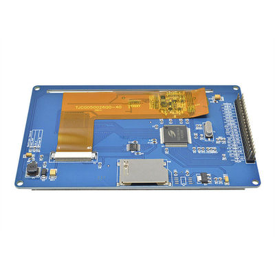
5.0 Inch LCD Display Module 800*480 SSD1963 8080 LCD TFT Module
Contact me for free samples and coupons.
Whatsapp:0086 18588475571
Wechat: 0086 18588475571
Skype: sales10@aixton.com
If you have any concern, we provide 24-hour online help.
xSize | 5inch | Resolution | 800*480 |
---|---|---|---|
Touch | Resistive Touch | Name | JC8048M050R |
Driver IC | SSD1963 | External Dimension | 135(L)X85(W)MM |
Highlight | 5.0 Inch LCD Display Module 800*480,LCD Display Module 800*480 SSD1963,SSD1963 8080 LCD TFT Module |
5.0 inch Resistive touch 5.0" 800*480 SSD1963 Smart Display Screen 5.0inch 8080 LCD TFT Module TFT display
● TFT power supply (pin name: 3.3V): screen power supply range is 3-3.3V; Remember not to use 5V,
The data level of all bus data pins shall not exceed 3.3V, remember
● Backlight power supply (pin name: 5V): the backlight power supply range is 4.5-7V, if the backlight power supply is low
At 4.5V, the backlight drive IC will be in the intermittent operation mode, which will appear as backlight
The IC will turn on and off, and the IC will be seriously heated, or even burnt out. Please note that.
● Backlight enable (pin name: LED_A): the module has inherited the backlight drive circuit, LED_ A
The high level backlight of the pin will be on, the low level backlight will be off, and the PWM signal will be Control brightness
Special description of parallel port 16-bit: TFT backlight current consumption of 4.3 inch and larger size is relatively large, (4.3 inch is the brightest
It is more than 200 ma when it is at its brightest, more than 300 ma when it is at its brightest in 5 inches, and more than 600 ma when it is at its brightest in 7 inches)
If USB power supply is used, there may be a situation that the current supply of some computer motherboards is not available,
It is also possible that the module will not work due to the poor quality of USB connection, which may cause serious partial voltage. please
Make sure your power supply is stable enough
Description:
1: Widely used
2: Support SPI FLASH
3: Built-in SD card slot, support SD card expansion
4: Support three backlight control methods (constant light, GPIO control, PWM control)
5: Support 800x480 resolution, the display effect is very clear
Product description:
- 5.0-inch high-definition color screen, support 16BIT RGB 65K color display, display rich colors
- Support 800x480 resolution, the display effect is very clear
- Support 16-bit parallel bus switching, fast transmission speed
- Compatible with capacitive touch screen and resistive touch screen
- Support SPI FLASH
- Built-in SD card slot, support SD card expansion
- Support three backlight control methods (constant light, GPIO control, PWM control)
- Provide sample programs for STM32 and C51 platforms
- Military-grade process standards, long-term stable work
- Provide underlying drive technology support
Notice:
The pins starting with A and T are related pins of the resistive touch screen;
B. The pins at the beginning of SD are SD card related pins;
The pins starting with C and F are related to SPI FLASH;
D. The rest are pins related to the LCD screen;
E. SPI FLASH is not soldered. If you need to use it, please solder it yourself.
Packing included:
1*touch screen
Name | Parameter |
SKU | JC8048M050R |
Display Color | RGB 565 |
Touch mode | Resistive touch |
Screen Size | 5.0(inch) |
Type | TFT |
Driver IC | SSD1963 |
Resolution | 800*480 (Pixel) |
Module Interface | 40PIN parallel port |
Active Area | 108.00(L))X64.80(W)MM |
External dimension | 135(L)X85(W)MM |
Operating Temperature | -20℃~60℃ |
Storage Temperature | -30℃~70℃ |
Operating Voltage | 3.3V |
Visual angle | 6:00 o'clock |
PIN spacing | PIN spacing |
Connection method | 2.54 pin |
Product Weight(Package containing) | 200g |
Interface Definition
Number | Pin Label | Pin Description |
1 | GND | Ground |
2 | 3.3V | 3.3V power input |
3 | NC | Empty feet |
4 | RS | Register/Data select signal, 0: Register 1: Data |
5 | WR | Write operation |
6 | RD | Read operation |
7 | DB8 | Data port |
8 | DB9 | Data port |
9 | DB10 | Data port |
10 | DB11 | Data port |
11 | DB12 | Data port |
12 | DB13 | Data port |
13 | DB14 | Data port |
14 | DB15 | Data port |
15 | CS | LCD chip select signal, active low |
16 | F_CS | Flash chip select |
17 | REST | LCD reset signal, low level reset |
18 | NC | Empty feet |
19 | LED_A | Backlight control positive |
20 | NC | Empty feet |
21 | DB0 | Data port |
22 | DB1 | Data port |
23 | DB2 | Data port |
24 | DB3 | Data port |
25 | DB4 | Data port |
26 | DB5 | Data port |
27 | DB6 | Data port |
28 | DB7 | Data port |
29 | T_CLK | Touch SPI bus clock signal |
30 | T_CS | Touch screen chip select signal, low level enable |
31 | T_DIN | Touch SPI bus input |
32 | NC | Empty feet |
33 | T_DO | Touch SPI bus output |
34 | T_IRQ | Touch screen interrupt signal, low level when there is touch |
35 | SD_DO | SD card data output pin |
36 | SD_CLK | SD card clock pin |
37 | SD_DIN | SD card data input pin |
38 | SD_CS | SD card select pin |
39 | NC | Empty feet |
40 | NC | Empty feet |